Bernoulli’s equation
The ideal fluid model
Real fluids have viscosity, an internal friction between layers of fluid that converts mechanical energy into thermal energy. We can relate pressure and flow speed by adding the additional assumption that the fluid is nonviscous, so no mechanical energy is dissipated as the fluid flows.
An incompressible, nonviscous fluid in steady, laminar flow is called an ideal fluid.
The continuity equation did not use this new assumption, so it holds for viscous fluids as well. The results in this section hold only for an ideal fluid. Blood is viscous, so we will add viscosity to the model in the chapter on viscosity.
Ideal flow and the energy principle
A nonviscous fluid has no internal friction, so we can analyze its flow with the energy principle with no change in thermal energy:
\[\Delta K + \Delta U_g + \Delta E_{\mathrm{th}} = W_{\mathrm{ext}}, \qquad \text{with } \Delta E_{\mathrm{th}} = 0.\]We will only consider horizontal flow, so that the height of the fluid does not change and $\Delta U_g = 0$. The only energy change we need to track is kinetic energy, and the only work is done by the pressure of the surrounding fluid.
The statement of the energy principle for ideal flow is called Bernoulli’s equation. It relates the pressure $p$ and the flow speed $v$ at two points along a streamline.
Work done by pressure forces
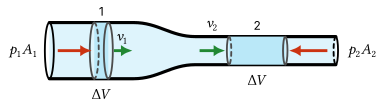
Choose our system to be the fluid in the tube between cross-section 1, in the wide part, and cross-section 2, in the narrow part. The fluid behind pushes forward on face 1 with force $p_1 A_1$, and the fluid ahead pushes backward on face 2 with force $p_2 A_2$.
In a short time $\Delta t$, face 1 moves forward by $v_1 \Delta t$ and face 2 by $v_2 \Delta t$. A volume $\Delta V = A_1 v_1 \Delta t = A_2 v_2 \Delta t$ enters at 1, and by continuity the same volume leaves at 2.
Derivation: Bernoulli’s equation
The pressure force $p_1 A_1$ acts in the direction of the displacement $v_1 \Delta t$, so it does positive work. The force $p_2 A_2$ acts opposite the displacement $v_2 \Delta t$, so it does negative work. The net work is
\[W_{\mathrm{ext}} = p_1 A_1 v_1 \Delta t - p_2 A_2 v_2 \Delta t = (p_1 - p_2)\,\Delta V.\]Since the flow is steady, the kinetic energy of the fluid in the middle of the system does not change. The net effect is that a volume $\Delta V$, of mass $\rho\,\Delta V$, has moved from the wide part (speed $v_1$) to the narrow part (speed $v_2$):
\[\Delta K = \tfrac{1}{2}\rho\,\Delta V\, v_2^2 - \tfrac{1}{2}\rho\,\Delta V\, v_1^2.\]With $\Delta U_g = 0$ and $\Delta E_{\mathrm{th}} = 0$, the energy principle gives $\Delta K = W_{\mathrm{ext}}$. Dividing both sides by $\Delta V$, we get $\tfrac{1}{2}\rho v_2^2 - \tfrac{1}{2}\rho v_1^2 = p_1 - p_2$.
Bernoulli’s equation for horizontal flow
Rearranging, we get Bernoulli’s equation for any two points along a horizontal streamline in an ideal fluid:
\[\boxed{p_1 + \tfrac{1}{2}\rho v_1^2 = p_2 + \tfrac{1}{2}\rho v_2^2.}\]Each term in this equation is an energy density or energy per unit volume. $\tfrac{1}{2}\rho v^2$ is the kinetic energy per unit volume, and $p$ is the work per unit volume that the pressure can do.
Pressure and flow speed
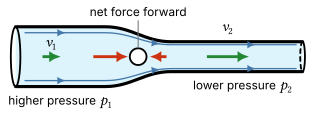
For horizontal ideal flow along a streamline, Bernoulli’s equation tells us that the pressure is lower where the flow speed is greater. Combining this with continuity, we find that the pressure decreases where a tube narrows and increases where it widens.
You might expect faster-moving fluid to exert a greater pressure. However, the fluid must accelerate as it enters the narrow section. This requires a greater pressure behind it than ahead of it, so the pressure must be lower where the fluid moves faster.
Why does the pressure decrease?
A fluid element entering the narrow section has to speed up, so by Newton’s second law it needs a net forward force. The only forces on it are the pushes from the surrounding fluid, so the pressure behind it must be larger than the pressure ahead of it.
In this horizontal ideal flow, the pressure difference $\Delta p$ provides the net force that accelerates the fluid toward the region of lower pressure.
Where does the pressure difference come from?
Fluid in the tapering section speeds up before it reaches the narrow section, so the pressure must already be lower ahead of it. How is this pressure difference set up in the first place?
Suppose the fluid is initially at rest, and we switch on a pump to start the flow. When flow first starts, fluid briefly arrives at the entrance to the narrowing faster than the narrow section carries it away. Real liquids are very slightly compressible, so the fluid just upstream is compressed by a tiny amount, and its pressure increases.
This pressure disturbance spreads to neighboring fluid at the speed of sound in the fluid, about $1500\ \mathrm{m/s}$ for water. The higher pressure behind the fluid entering the narrowing pushes it forward and accelerates it until the flow satisfies continuity everywhere.
In steady flow, fluid no longer accumulates anywhere and the density is uniform, but the pressure differences remain. The incompressible model neglects the tiny initial density changes that set up the pressure field.
Example: A narrowing pipe
Water flows through a horizontal pipe. At one point, where the pipe has diameter $25\ \mathrm{mm}$, the flow speed is $0.26\ \mathrm{m/s}$. The pipe then narrows to a diameter of $15\ \mathrm{mm}$ and ends in an opening where the water leaves the pipe. (Assume the water at the opening is at atmospheric pressure.)
(a) What is the flow speed in the narrow section of the pipe?
(b) What is the pressure in the wide section of the pipe?
(c) What volume of water leaves the pipe in $1.0\ \mathrm{min}$?
Solution
(a) Label the wide section 1 and the narrow section 2. Since $A \propto d^2$, the continuity equation gives
\[v_2 = \frac{A_1}{A_2}\, v_1 = \left(\frac{d_1}{d_2}\right)^{2} v_1 = \left(\frac{25\ \mathrm{mm}}{15\ \mathrm{mm}}\right)^{2}(0.26\ \mathrm{m/s}) = \boxed{0.72\ \mathrm{m/s}}.\](b) The water leaves the opening at atmospheric pressure. The narrow section has a uniform diameter, so the flow speed, and by Bernoulli’s equation the pressure, is the same all along it: $p_2 = p_{\mathrm{atm}}$. Bernoulli’s equation gives
\[p_1 = p_{\mathrm{atm}} + \tfrac{1}{2}\rho\left(v_2^2 - v_1^2\right) = 101.3\ \mathrm{kPa} + 0.23\ \mathrm{kPa} = \boxed{101.5\ \mathrm{kPa}}.\]The gauge pressure in the wide section is only $0.23\ \mathrm{kPa}$.
(c) The volume flow rate is
\[Q = A_1 v_1 = \pi(0.0125\ \mathrm{m})^2(0.26\ \mathrm{m/s}) = 1.28\times 10^{-4}\ \mathrm{m^3/s},\]so in $60\ \mathrm{s}$ the volume that leaves the pipe is
\[\Delta V = Q\,\Delta t = (1.28\times 10^{-4}\ \mathrm{m^3/s})(60\ \mathrm{s}) = 7.7\times 10^{-3}\ \mathrm{m^3} = \boxed{7.7\ \mathrm{L}}.\]The Venturi meter
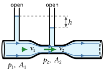
A Venturi meter uses the pressure decrease in a narrowing pipe to measure the flow rate. Vertical pipes attached to the wide and narrow sections show the pressure.
The fluid in each vertical pipe is at rest, so we can use the static fluid pressure equation to relate the height of each column to the pressure in the pipe below it. The pressure is lower in the narrow section, so its column is lower. A height difference $h$ corresponds to a pressure difference $p_1 - p_2 = \rho g h$.
Example: Reading a Venturi meter
Water flows through a horizontal Venturi meter whose inlet has diameter $4.0\ \mathrm{cm}$ and whose throat has diameter $2.0\ \mathrm{cm}$. The water column in the standpipe above the inlet stands $12\ \mathrm{cm}$ higher than the column above the throat. Find the flow speed in the inlet and the volume flow rate through the pipe.
Solution
Label the inlet 1 and the throat 2. The throat’s diameter is half the inlet’s diameter. Since $A \propto d^2$, its area is one quarter of the inlet’s area, and the continuity equation gives
\[v_2 = \frac{A_1}{A_2}\, v_1 = \left(\frac{d_1}{d_2}\right)^{2} v_1 = 4 v_1.\]Bernoulli’s equation gives the pressure difference in terms of the speeds:
\[p_1 - p_2 = \tfrac{1}{2}\rho\left(v_2^2 - v_1^2\right) = \tfrac{1}{2}\rho\left(16 v_1^2 - v_1^2\right) = \tfrac{15}{2}\rho v_1^2.\]The standpipes are static columns of water, so hydrostatics gives the same pressure difference in terms of $h$:
\[p_1 - p_2 = \rho g h.\]Setting the two expressions for $p_1 - p_2$ equal gives $\tfrac{15}{2}\rho v_1^2 = \rho g h$. The density cancels, and solving for $v_1$,
\[v_1 = \sqrt{2 g h/15} = \sqrt{2(9.8\ \mathrm{m/s^2})(0.12\ \mathrm{m})/15} = \boxed{0.40\ \mathrm{m/s}}.\]The volume flow rate is then
\[Q = v_1 A_1 = (0.396\ \mathrm{m/s})\,\pi(0.020\ \mathrm{m})^2 = \boxed{5.0\times 10^{-4}\ \mathrm{m^3/s}} = 0.50\ \mathrm{L/s}.\]Notice that the density canceled. In the ideal-fluid model, the flow speed depends only on the height difference and the tube dimensions, not on the density of the fluid.
Applications: the circulatory system
Stenosis
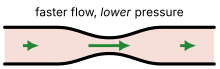
An arterial stenosis is a narrowing of an artery, for example by plaque. By continuity the blood speeds up in the narrowed region, and Bernoulli’s equation predicts that its pressure there decreases.
After the narrowing, the pressure increases again, but it does not return to its original value. The fast jet breaks up into swirling eddies, and friction within the blood converts some of its mechanical energy into thermal energy. We will study viscosity and turbulence in the chapters that follow.
The disturbed flow past a stenosis can produce a sound (a bruit) heard with a stethoscope.
Aneurysm
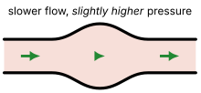
An aneurysm is a bulge in a weakened artery wall. By continuity the blood slows down in the bulge, and Bernoulli’s equation predicts that its pressure increases, but only slightly.
The increased radius also affects the artery wall. A wider vessel requires a greater wall tension to support the same blood pressure (due to Laplace’s law). As an aneurysm grows, the stress on its already weakened wall increases.
Bernoulli in the circulation?
Check your understanding: Blood flows through the aorta at about $0.3\ \mathrm{m/s}$ and through the capillaries at about $0.4\ \mathrm{mm/s}$. Treating blood as an ideal fluid with $\rho = 1060\ \mathrm{kg/m^3}$ and comparing points at the same height, what does Bernoulli’s equation predict for the pressure in the capillaries compared with the aorta? The measured mean pressures are about $95\ \mathrm{mmHg}$ in the aorta and $35\ \mathrm{mmHg}$ at the entrance to the capillaries. What does the comparison tell you?
Answer
The blood is much slower in the capillaries, so Bernoulli’s equation predicts a capillary pressure higher than the aortic pressure, by
\[\tfrac{1}{2}\rho\left(v_a^2 - v_c^2\right) \approx \tfrac{1}{2}(1060\ \mathrm{kg/m^3})(0.3\ \mathrm{m/s})^2 = 48\ \mathrm{Pa} = 0.36\ \mathrm{mmHg}.\]The measured pressure is about $60\ \mathrm{mmHg}$ lower. The ideal fluid model is not even close: the pressure drop is due to viscous dissipation, which we study in the chapter on viscosity.
What the ideal fluid model misses
In the ideal fluid model, the pressure in a horizontal tube changes only where the speed changes. A long, uniform, horizontal pipe would carry fluid with no pressure drop at all, and no pump would be needed to keep it flowing.
In the real systemic circulation, the mean blood pressure decreases from about $95\ \mathrm{mmHg}$ in the aorta to a few mmHg where the veins return blood to the heart. The heart must work continuously to keep the blood moving.
This pressure drop occurs because viscosity converts mechanical energy into thermal energy. In the chapter on viscosity, we will include viscosity in our model and find out which vessels are responsible for most of the drop.