Torque
A particle is in equilibrium if its motion is not changing: it is either at rest or moving with constant velocity. Equivalently, being in equilibrium means the net force on the particle is zero.
Real objects are not point particles! They are extended objects that, in addition to moving through space, can rotate about an axis. For an extended object, being in equilibrium also means that this rotation is not changing.
If we want to understand how forces from our muscles, joints, and connective tissues support our bodies and external loads, we need to understand the conditions for equilibrium of extended objects.
Torque is the rotational equivalent of force
We can think of a force as a push or a pull that changes the motion of an object. A force applied away from a pivot point leads to a “twist” that tends to change the rotation of the object about that pivot. We call this twist a torque.
For example, if you hold a heavy book in your outstretched hand, the contact force from the book on your hand creates a torque about your shoulder that tends to rotate your arm downwards. The strength of this torque depends on the magnitude of the force and how far away from your shoulder it is applied.
Similarly, if you want to push open a door, you apply the force on the door handle, which is located far from the hinges. If you try to push the door near the hinges, you will need to apply a much larger force to create the same torque and open the door.
Torque is relative to the pivot point
The torque $\tau$ exerted by a force $\vec{F}$ is always calculated relative to a chosen pivot point $P$. The same force can exert a different torque depending on our choice of pivot point.
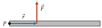
We will define the position vector $\vec{r}$ as the vector from the pivot point $P$ to the point where the force $\vec{F}$ acts.
Torque depends on distance from the pivot
The torque exerted by a force is proportional to the distance $r$ from the pivot point; this distance is the magnitude of the position vector, $r = \lvert\vec{r}\rvert$. The larger the distance $r$, the larger the torque exerted by the same force.
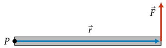
If a force is applied at the pivot point (a distance of $r = 0$) it exerts zero torque. That is, a force applied at the pivot does not tend to rotate the object about that point.
Torque depends on the direction of the force
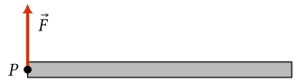
The torque exerted by a force depends on the direction of the force. A force exerted along the line from the pivot to the point of application (parallel to the position vector $\vec{r}$) exerts zero torque.

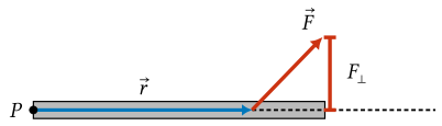
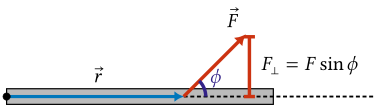
Only the component of the force that is perpendicular ($\perp$) to the position vector $\vec{r}$ contributes to the torque. The torque is proportional to the magnitude of this perpendicular component, which we label $F_\perp$.
Angle between force and position vector
We can write the perpendicular component of the force in terms of the angle $\phi$ between the force $\vec{F}$ and the position vector $\vec{r}$. To find the angle between $\vec{r}$ and $\vec{F}$, place them with their tails together:
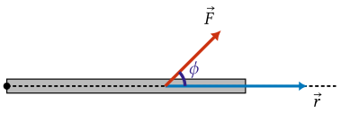
We can also determine the angle by extending the line parallel to the position vector $\vec{r}$ past the point where the force acts, and then measuring the angle of the force from this line:
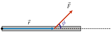
The perpendicular component of the force can be found from the angle $\phi$ using trigonometry. Since the perpendicular component is opposite the angle $\phi$, we have $F_\perp = F\sin\phi$.
Calculating the magnitude of torque
Since the torque is proportional to both the distance $r$ and the perpendicular component of the force $F_\perp$, we can write the magnitude of the torque as follows.
Key result: The magnitude of the torque is \(\boxed{\lvert\tau\rvert = r F \sin\phi}\)
In this formula:
- $r$ is the distance from the pivot to the point where the force is applied. It is the magnitude of the position vector $\vec{r}$ pointing from the pivot to the force.
- $F = \lvert\vec{F}\rvert$ is the magnitude of the force.
- $\phi$ is the angle between the position vector $\vec{r}$ and the force $\vec{F}$.
Since $r$ has units of $\mathrm{m}$ and $F$ has units of $\mathrm{N}$, the units of torque are newton meters ($\mathrm{N \cdot m}$).
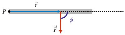
Check your understanding: A force $\vec{F}$ acts straight down on a horizontal rod, at a distance $r$ from the pivot $P$. What is the angle $\phi$ between $\vec{r}$ and $\vec{F}$, and what does the formula $\lvert\tau\rvert = rF\sin\phi$ become in this case?
Answer
The position vector $\vec{r}$ points from the pivot along the rod to the point where the force acts, so it is horizontal. The force $\vec{F}$ points straight down. The angle between a horizontal direction and a vertical direction is a right angle:
\[\boxed{\phi = 90^\circ.}\]Since $\sin 90^\circ = 1$, the sine factor drops out of the torque formula and the magnitude of the torque is simply the product of the distance and the force:
\[\boxed{\lvert\tau\rvert = rF.}\]This is the largest torque a force of magnitude $F$ can produce at a distance $r$ from the pivot, because $\sin\phi$ is never larger than 1. A force applied perpendicular to the rod is the most effective at rotating it.
A force perpendicular to the position vector
When the force acts perpendicular to the position vector, the angle between them is $\phi = 90^\circ$. Since $\sin 90^\circ = 1$, the sine factor drops out and the magnitude of the torque is just the product of the distance and the force:
Key result: For $\vec{F}$ and $\vec{r}$ perpendicular, \(\boxed{\lvert\tau\rvert = rF}\)
This is the largest torque that a force of magnitude $F$ can exert at a distance $r$ from the pivot, because $\sin\phi$ is never larger than 1.
Moment arm and torque
We can also express the torque in terms of the moment arm $r_\perp$, which is the distance from the pivot to the force measured perpendicular to the force. In other words, the moment arm $r_\perp$ is the component of the position vector $\vec{r}$ along the direction perpendicular to the force.
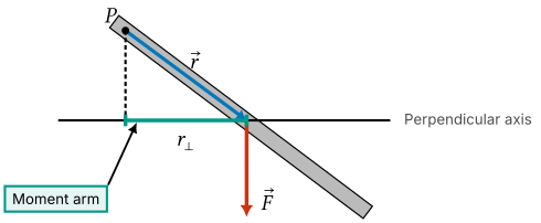
The moment arm is opposite the angle $\phi$, so we can also write $r_\perp = r\sin\phi$.
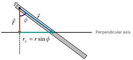
Calculating torque using the moment arm
Rearranging our earlier formula for the magnitude of the torque, we have
\[\lvert\tau\rvert = r F \sin\phi = (r\sin\phi) F = r_\perp F\]Key result: In terms of the moment arm, the magnitude of the torque is \(\boxed{\lvert\tau\rvert = r_\perp F}\)
In this formula:
- $r_\perp$ is the moment arm, which is the distance from the pivot to the force measured perpendicular to the force.
- $F$ is the magnitude of the force.
Finding the moment arm
The moment arm formula is often the most practical way to calculate the torque exerted by a force. To use this formula, we need to find the moment arm $r_\perp$ for the force. To find the moment arm:
- Draw the position vector $\vec{r}$ from the pivot to the point where the force is applied.
- Draw axes parallel and perpendicular to the force through the point of application.
- Draw the component of the position vector along the perpendicular axis. The length of this component is the moment arm $r_\perp$.
- Use trigonometry to find the length of the moment arm if it is not given directly.
The moment arm formula for the torque is easiest to apply when the force is either vertical or horizontal.
For a vertical force, the moment arm is the horizontal component of the displacement.
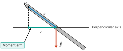
For a horizontal force, the moment arm is the vertical component of the displacement.
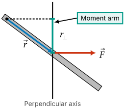
Example: Moment arms for an angled rod
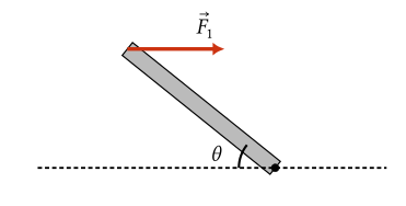
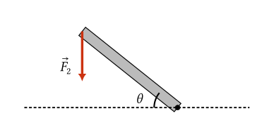
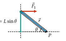
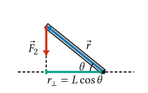
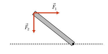
A force $\vec{F}_1$ is applied horizontally to the end of a thin rod as shown. The rod has length $L$ and is at angle $\theta$ from the horizontal. Find the moment arm $r_\perp$ for this force about the given pivot point in terms of $L$ and $\theta$. Then repeat the exercise for the force $\vec{F}_2$ applied vertically downward to the end of the rod.
Solution
For the horizontal force $\vec{F}_1$, the moment arm is the perpendicular (vertical) distance from the pivot to the line of the force:
For the vertical force $\vec{F}_2$, the moment arm is the perpendicular (horizontal) distance from the pivot to the line of the force:
Sign of torque and the right-hand rule
The torque $\tau$ is a signed quantity, with the sign indicating the direction of rotation that the torque tends to produce about the pivot. The sign convention for torque is:
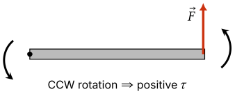
- A torque that tends to produce counterclockwise (CCW) rotation about the pivot is positive.
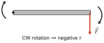
- A torque that tends to produce clockwise (CW) rotation about the pivot is negative.
For example, an upward force at the right end tends to rotate the rod counterclockwise about the pivot. This force exerts a positive torque about the pivot.
On the other hand, a downward force at the right end tends to rotate the rod clockwise about the pivot. This force exerts a negative torque about the pivot.
Determining the sign of torque
In many cases, you can tell just by looking at the direction of the force whether it produces a positive or negative torque about the pivot. In cases where it is not obvious, we can find the sign of the torque by using the right-hand rule (RHR). To use the RHR:
- Point the fingers of your right hand in the direction of the position vector $\vec{r}$ from the pivot to the point where the force is applied.
- Face your palm and/or bend your fingers in the direction of the force $\vec{F}$.
- If your thumb points out of the page (toward you) the torque is positive (CCW). If your thumb points into the page (away from you) the torque is negative (CW).
Check your understanding: Use the right-hand rule to determine the sign of the torque about the given pivot point due to each of the forces $\vec{F}_1$ and $\vec{F}_2$ shown in the figure. (These are the same forces as in the moment-arm example above.)
Answer
For the horizontal force $\vec{F}_1$, the right-hand rule shows that the force tends to rotate the rod clockwise about the pivot, so its torque is negative. Combining this with the moment arm found in the example above,
\[\boxed{\tau_1 = -F_1 L\sin\theta.}\]For the vertical force $\vec{F}_2$, the right-hand rule shows that the force tends to rotate the rod counterclockwise about the pivot, so its torque is positive:
\[\boxed{\tau_2 = +F_2 L\cos\theta.}\]Calculating torque
Calculating the torque exerted by a force takes multiple steps:
- Draw the position vector $\vec{r}$ from the pivot to the point where the force is applied.
- Decide whether to use the moment arm formula $\lvert\tau\rvert = r_\perp F$ or the angle formula $\lvert\tau\rvert = rF\sin\phi$. Default to the moment arm for horizontal or vertical forces.
- If using the moment arm formula, find the moment arm $r_\perp$ for the force. If using the angle formula, find the angle $\phi$ between $\vec{r}$ and $\vec{F}$.
- Calculate the magnitude of the torque using the appropriate formula.
- Determine the sign of the torque using the right-hand rule if it is not obvious from the direction of the force.
- Write the final answer for the torque, either $\tau = +\lvert\tau\rvert$ or $\tau = -\lvert\tau\rvert$ depending on the sign.
Net torque
The net torque about a pivot is the sum of the torques exerted by all the forces acting on the object about that pivot:
\[\tau_\text{net} = \tau_1 + \tau_2 + \tau_3 + \ldots\]Note that we must add the torques with their signs.
Example: Net torque on a tilted rod
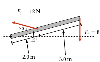
Calculate the net torque about the pivot point $P$ due to the two forces $\vec{F}_1$ and $\vec{F}_2$ shown in the figure, applied to a straight rod that is tilted $15^\circ$ above the horizontal. $\vec{F}_1$ has magnitude $12\ \mathrm{N}$, acts $2.0\ \mathrm{m}$ from the pivot, and is directed at $30^\circ$ from the long axis of the rod. $\vec{F}_2$ has magnitude $8.0\ \mathrm{N}$, acts at the far end of the rod, and points straight down. The far end is $3.0\ \mathrm{m}$ farther along the rod from the point where $\vec{F}_1$ acts.
Solution
For $\vec{F}_1$, the angle between the position vector $\vec{r}_1$ and the force is $150^\circ$, which has the same sine as $30^\circ$. The force tends to rotate the rod counterclockwise, so
\[\begin{aligned} \tau_1 &= +r_1 F_1 \sin(150^\circ)\\ &= +(2.0\ \mathrm{m})(12\ \mathrm{N})\sin(30^\circ)\\ &= +12\ \mathrm{N \cdot m}. \end{aligned}\]For $\vec{F}_2$, the moment arm is the horizontal distance from the pivot to the far end of the rod:
\[r_{\perp,2} = (2.0\ \mathrm{m} + 3.0\ \mathrm{m})\cos(15^\circ).\]The downward force at the right side of the pivot produces a clockwise torque, so
\[\begin{aligned} \tau_2 &= -F_2 r_{\perp,2}\\ &= -(8.0\ \mathrm{N})(5.0\ \mathrm{m})\cos(15^\circ)\\ &= -38.6\ \mathrm{N \cdot m}. \end{aligned}\]Adding the torques with their signs,
\[\begin{aligned} \tau_{\mathrm{net}} &= \tau_1 + \tau_2\\ &= 12\ \mathrm{N \cdot m} - 38.6\ \mathrm{N \cdot m}\\ &= -26.6\ \mathrm{N \cdot m}. \end{aligned}\]To two significant figures,
\[\boxed{\tau_{\mathrm{net}} = -27\ \mathrm{N \cdot m}.}\]The negative sign means the net torque is clockwise.