Using Newton’s second law
Newton’s 2nd law (N2) will be our main tool for solving force problems, so it is worth giving it some further attention before we move on to applying it.
N2 is a vector equation relating the net force vector $\vec{F}_{\mathrm{net}}$ acting on an object to the acceleration vector $\vec{a}$ of the object: $\vec{F}_{\mathrm{net}} = m\vec{a}$. Because N2 is a vector equation, you should really think of it as two separate equations, one for each component:
\[\boxed{ \begin{aligned} F_{\mathrm{net},x} &= m a_x \\ F_{\mathrm{net},y} &= m a_y \end{aligned} }\]In order to write down the components of the net force on an object, we first need to identify all of the forces acting on the object and then decompose each force into its $x$ and $y$ components.
Although Newton’s second law is simple to state, it takes some work to apply it to solve problems. The process for applying Newton’s second law to solve problems generally follows these steps:
- Choose the system to consider.
- Identify forces acting on the system and draw a free-body diagram for the system.
- Identify acceleration constraints.
- Choose convenient coordinate axes.
- Decompose forces and add components to get $F_{\mathrm{net},x}$ and $F_{\mathrm{net},y}$.
- Use Newton’s 2nd law equations and constraint equations to solve.
Let’s walk through these steps before we introduce some specific forces and use them in examples.
System and environment
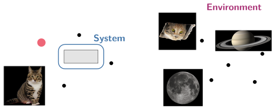
A system is any collection of objects that we choose. Our choice of system is completely arbitrary. Once we choose a system, everything in the universe outside of the system is called the environment. For now, we will mostly choose our system to consist of a single object, which we will model as a point particle.
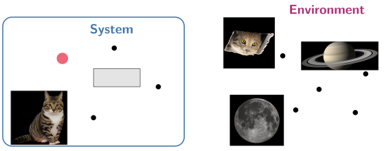
Because the choice is ours, we can also draw the system boundary differently — for example, around just the gray block — and everything else, including the first cat and the red ball, becomes part of the environment:
Identifying forces
Every force on a system represents an interaction between the system and its environment. To help you identify forces, think about all of the objects in the environment that the system is interacting with. Each object will exert a corresponding force on the system.
| Object in environment | Force |
|---|---|
| Earth | Gravitational force (weight) $\vec{w}$ |
| Stretched object (e.g., string) | Tension $\vec{F}_T$ |
| Surface (e.g., floor or table) | Normal force $\vec{F}_N$ (perpendicular to surface); friction $\vec{f}$ (parallel to surface) |
| Spring | Spring force $\vec{F}_{\mathrm{sp}}$ |
| Fluid | Fluid resistance (drag) $\vec{F}_d$ |
| External agent (e.g., a person) | Applied force (catch-all term) |
Free-body diagrams
To help organize and picture the forces acting on a system, we draw a free-body diagram (FBD) for the system. A FBD is a vector diagram showing all of the force vectors acting on your chosen system, and only those forces that act on the system.
Since we model objects as point particles, we represent the system as a single point in the FBD, and we draw all of the forces as vectors at that point.
Check your understanding: Try it yourself: (1) Draw a free-body diagram for a book resting on a table. (2) Draw a free-body diagram for a book being pushed across a table.
Constraints
The next step in our list is to identify acceleration constraints that apply to the system. A constraint is a condition we need to add to a problem that isn’t determined by the forces. Constraints add mathematical conditions (constraint equations) to a problem that we can’t get from Newton’s 2nd law.
Some examples of physical constraints we will see and translate into mathematical equations:
- Objects can’t pass through solid surfaces.
- Two objects attached by a taut string move together.
- If you push one block against another block, the blocks move together.
- An object supported by a string doesn’t fall down.
All of the constraint equations we will use in the course are conditions on the acceleration of the system. For example, if two objects are attached by a taut string, they must have the same acceleration parallel to the string.
The contact constraint
One of the most common constraints we will see is what I will call the contact constraint, which applies when an object is in contact with a solid surface. Since the surface prevents the object from passing through it, the object does not move perpendicular to the surface.
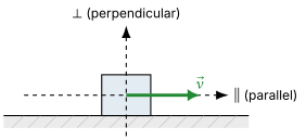
For a flat, stationary surface, the contact constraint tells us that the component of the acceleration perpendicular to the surface is zero:
\[a_\perp = 0\]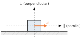
Convenient coordinates
After we identify the constraints, we want to choose coordinate axes that make it easy to apply the constraints and Newton’s 2nd law. The coordinates that are “convenient” in a given problem are determined by the constraints in the problem.
For example, if an object is constrained to move along a surface, we usually want to choose one axis parallel to the surface and one axis perpendicular to the surface.
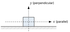
These are convenient coordinate axes for a block on a horizontal surface. Since the $y$-axis is perpendicular to the surface, the contact constraint is simply $a_y = 0$.
This is the case even if the surface is not horizontal, such as an inclined plane. In this case, we will typically choose “tilted” coordinate axes aligned with the surface: one axis parallel to the surface and one axis perpendicular to the surface.
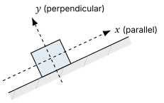
With these tilted axes for a block on an inclined surface, the $y$-axis is still perpendicular to the surface, so the contact constraint is still just $a_y = 0$.
Once we have chosen our coordinate axes, we need to decompose all of the forces we drew in the free-body diagram into components along those axes to write down the Newton’s 2nd law equations. We are now at the point where we want to introduce some specific forces and see how to use them in Newton’s 2nd law equations.
Weight and contact forces
The weight force
The Earth exerts a gravitational force on all objects near its surface. The gravitational force the Earth exerts on an object is also called the weight of the object, and we denote it by $\vec{w}$. The weight force on an object with mass $m$ has magnitude
\[\boxed{w = mg}\]and points down toward the Earth.
Note the distinction between weight and mass:
- Mass is an intrinsic property of an object that measures how difficult it is to change the object’s motion.
- Weight is a force exerted on an object by the Earth.
Contact forces: the normal force
Two objects in contact exert forces on each other. We can understand how these forces arise from the internal structure of the objects using a simple microscopic model.
We can picture a solid object as a lattice of atoms held in place by stiff, spring-like molecular bonds. When one object is in contact with the surface of another object, the bonds in the surface compress. The compressed bonds push back outward, exerting a compression force perpendicular to the surface that prevents the object from passing through the surface.
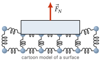
In mathematical jargon, the word normal means “perpendicular.” Because the compression force exerted by a surface acts perpendicular to the surface, this force is called the normal force $\vec{F}_N$.
Contact forces like the normal force are examples of constraint forces. A constraint force will take whatever value it needs to in order for the system to satisfy a constraint. For the normal force, the relevant constraint is the contact constraint—the normal or compression force exerted by a surface is what prevents objects from passing through the surface.
To determine the magnitude of the normal force: write down the net force in the direction perpendicular to the surface and set it equal to zero, using the contact constraint $a_\perp = 0$. We can solve the resulting equation for the normal force.
Example: Determining the normal force
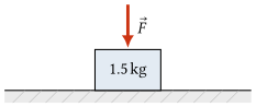
A $1.5\ \mathrm{kg}$ textbook rests on a horizontal table, and you push straight down on the book with a force of magnitude $5.0\ \mathrm{N}$. What is the magnitude of the normal force from the table on the book?
Solution
Take the $+y$ axis pointing upward. The book is in contact with the table, and the contact constraint tells us that $a_y = 0$. The forces on the book are the normal force upward, the weight downward, and the applied push downward.
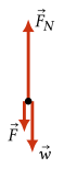
Newton’s second law (N2) in the $y$ direction gives
\[\begin{aligned} F_{\mathrm{net},y} &= m a_y\\ F_N - mg - F &= 0. \end{aligned}\]Solving for the normal force,
\[\begin{aligned} F_N &= mg + F\\ &= \left(1.5\ \mathrm{kg}\right)\!\left(9.8\ \mathrm{m/s^2}\right) + 5.0\ \mathrm{N}\\ &= 19.7\ \mathrm{N}. \end{aligned}\]To two significant figures, the normal force is
\[\boxed{F_N = 20\ \mathrm{N}.}\]The normal force is larger than the book’s weight because the table must support both the book’s weight and the extra downward push.
Contact forces: tension
A string, rope, or similar extended object can also be modeled as a lattice of atoms held together by spring-like bonds, arranged in long chains along its length. When you pull on a string, you stretch these bonds. The stretched bonds pull back inward along the string, exerting a tension force $\vec{F}_T$.
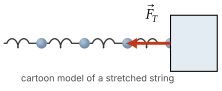
Normal force and tension are two manifestations of the microscopic electric interactions between atoms. In the case of the normal force, compressed bonds push the objects apart, while in the case of tension, stretched bonds pull the objects together.
The tension force exerted by a stretched string is always a “pulling” force that points away from the object along the length of the string.
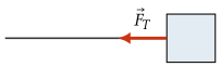
We will always assume that the tension in a string has the same magnitude everywhere along the string.
Like the normal force, the tension in a string is a constraint force: its magnitude is determined by the constraints in the problem (that is, the known accelerations) and it takes whatever value is necessary to satisfy those constraints.
Example: Tension in cables
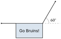
A $5.0\ \mathrm{kg}$ banner is held in place by two cables, one horizontal and one at an angle of $60^\circ$ above the horizontal. Calculate the magnitude of the tension in each of the cables.
Solution
Let $F_1$ be the tension in the horizontal cable and $F_2$ be the tension in the angled cable. The banner is at rest, so $a_x = 0$ and $a_y = 0$.
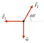
The tension in the angled cable has horizontal and vertical components
\[F_{2,x} = F_2\cos(60^\circ), \qquad F_{2,y} = F_2\sin(60^\circ).\]The vertical N2 equation gives
\[\begin{aligned} F_{\mathrm{net},y} &= m a_y\\ F_2\sin(60^\circ) - mg &= 0\\ F_2 &= \frac{mg}{\sin(60^\circ)}\\ &= \frac{\left(5.0\ \mathrm{kg}\right)\left(9.8\ \mathrm{m/s^2}\right)}{\sin(60^\circ)}\\ &= 56.6\ \mathrm{N}. \end{aligned}\]The horizontal N2 equation gives
\[\begin{aligned} F_{\mathrm{net},x} &= m a_x\\ F_2\cos(60^\circ) - F_1 &= 0\\ F_1 &= F_2\cos(60^\circ)\\ &= \left(56.6\ \mathrm{N}\right)\cos(60^\circ) = 28.3\ \mathrm{N}. \end{aligned}\]To two significant figures,
\[\boxed{F_2 = 57\ \mathrm{N}}, \qquad \boxed{F_1 = 28\ \mathrm{N}.}\]Solving force problems
Decomposing the weight on an incline
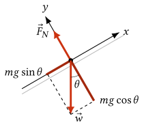
If we choose the positive $x$-axis up the incline and the positive $y$-axis perpendicular to the surface (pointing away from the incline), then the angle of the weight vector from the $-y$-axis is the same as the angle of the incline.
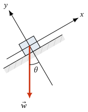
Since the weight force always points down, any time we have an object on an incline and we choose axes parallel and perpendicular to the incline, the components of the weight will be
\[\begin{aligned} w_x &= -mg\sin\theta,\\ w_y &= -mg\cos\theta. \end{aligned}\]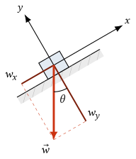
Example: An object on an incline
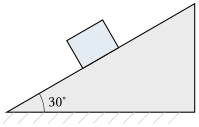
A $1.5\ \mathrm{kg}$ textbook slides down a smooth inclined surface that is tilted at an angle of $30^\circ$ from the horizontal. Assume that the surface is smooth enough that we can ignore friction.
- What is the magnitude of the normal force from the surface on the book?
- What is the acceleration of the book?
Solution
Choose the $+x$ axis up the incline and the $+y$ axis perpendicular to the surface, pointing away from the incline. In these coordinates, the angle of the weight force from the $-y$ axis is the same angle $\theta$ as the angle of the incline. The weight components are
\[w_x = -mg\sin\theta, \qquad w_y = -mg\cos\theta.\]The book stays in contact with the surface, so the contact constraint is $a_y = 0$.
(a) Newton’s second law in the perpendicular direction gives
\[\begin{aligned} F_{\mathrm{net},y} &= m a_y\\ F_N - mg\cos\theta &= 0. \end{aligned}\]Therefore,
\[\begin{aligned} F_N &= mg\cos\theta\\ &= \left(1.5\ \mathrm{kg}\right)\left(9.8\ \mathrm{m/s^2}\right)\cos(30^\circ)\\ &= \boxed{13\ \mathrm{N}.} \end{aligned}\](b) There is no friction, so the only force component parallel to the incline is $w_x = -mg\sin\theta$. Newton’s second law along the incline gives
\[\begin{aligned} F_{\mathrm{net},x} &= m a_x\\ -mg\sin\theta &= m a_x\\ a_x &= -g\sin\theta\\ &= -\left(9.8\ \mathrm{m/s^2}\right)\sin(30^\circ) = -4.9\ \mathrm{m/s^2}. \end{aligned}\]The negative sign means the acceleration points down the incline. The magnitude of the acceleration is
\[\boxed{4.9\ \mathrm{m/s^2}\text{ down the incline}.}\]